
1. A common task for the comparison
Consider a spacecraft relocating from a 500 km circular Earth orbit to a 1,000 km circular orbit in the same plane. Its payload and common spacecraft hardware weigh 100 kg. Propulsion equipment, propellant and any additional power or thermal hardware must be added separately.
We examine three operating constraints:
| Case | Readiness deadline | Propulsion electrical allocation |
|---|---|---|
| Baseline | 30 days | 200 W |
| Shorter deadline | 48 hours | 200 W |
| Greater available power | 30 days | 1,000 W |
The destination remains unchanged. What changes is the time and electrical power available to reach it. The power allocation is measured at the complete propulsion-system input during permitted operation, not at the solar-array output or thruster discharge. The deadline includes the preparation needed before useful operations begin; the particular arrival tolerances and readiness activities have not yet been assigned numerical allowances.
These illustrative cases let us examine how propulsion choices affect propellant consumption, powered duration and spacecraft installation. The comparison begins with those resource requirements, then considers what must be added—and verified—to turn a candidate into an operational system. This is not a selection of flight hardware or a solved transfer schedule.
2. Propellant needed for the relocation
The idealized transfer calculations give a velocity-change requirement of approximately 262 m/s. For this modest altitude increase, the two-impulse transfer and slowly expanding circular spiral have nearly the same reference velocity increment; their different powered durations will become important in the next section.
For constant effective specific impulse, the maneuver propellant is:
Here, is the spacecraft mass remaining after the maneuver, is specific impulse, and . The remaining mass includes the common spacecraft hardware, the propulsion installation and any reserves or unusable residuals still onboard. This is the ideal rocket equation rearranged to calculate propellant consumption.
Because the installations have not been sized, the table expresses consumption per 100 kg remaining after the maneuver. That is a scaling reference, not the complete mass of the spacecraft introduced above. Multiply each row by its own candidate's actual remaining mass divided by 100 kg.
| Illustrative reference | Assumed specific impulse | Propellant expelled per 100 kg remaining |
|---|---|---|
| Nitrogen cold gas | 70 s | 46.56 kg |
| Hydrazine monopropellant | 220 s | 12.93 kg |
| Conventional bipropellant, MMH/NTO-family informed | 290 s | 9.67 kg |
| Hall-electric | 1,400 s | 1.93 kg |
Calculation basis: the first three rows use 262.389 m/s from the ideal two-impulse transfer; the Hall row uses 262.470 m/s from the slow, near-circular tangential-spiral approximation. These are constant-specific-impulse resource calculations, not propagated finite-burn trajectories. The orbit model, constants and input provenance are listed in the calculation and reference notes.
At equal remaining spacecraft mass, the selected bipropellant reference expels approximately 25% less maneuver propellant than the hydrazine reference. The Hall reference reduces that quantity further, while the cold-gas reference requires substantially more propellant for this particular relocation.
These rows are selected reference points, not limits for their respective technologies. In particular, green monopropellants based on ammonium dinitramide (ADN) or hydroxylammonium nitrate (HAN) can improve on hydrazine's specific impulse and density-specific impulse—the product of propellant density and specific impulse. The 220 s row does not represent those systems. NASA propulsion assessment
The mass differences give us a starting point for the installation comparison. Initial spacecraft mass also depends on the equipment and retained consumables each candidate requires. Startup consumption is outside this calculation. Next, we examine how long the propulsion must operate and what the power allocation permits.
3. Powered time and the readiness deadline
For constant thrust and effective specific impulse, the modeled propellant consumption gives the required powered duration:
The numerator is total impulse, and is thrust. This follows from the specific-impulse and total-impulse definitions. The time is the sum of firing intervals, not the elapsed time from departure to readiness for useful operations.
First, apply the same illustrative 10 N thrust level to the cold-gas and chemical references:
| Reference | Conditional powered time per 100 kg remaining, at 10 N |
|---|---|
| Nitrogen cold gas, 70 s | 53.3 minutes |
| Hydrazine monopropellant, 220 s | 46.5 minutes |
| Conventional bipropellant, 290 s | 45.8 minutes |
At an assumed 1 N, these powered durations would be ten times longer. These are thrust-level sensitivities, not claims that the cited products deliver every listed operating point or support the required firing duty. At equal thrust and remaining mass, the two selected chemical references have similar powered durations; their more substantial difference in this example is propellant consumption.
Even the 10 N durations are not instantaneous burns. A finite-thrust trajectory and operating schedule are needed before stating the actual arrival time. Adding the ideal Hohmann coast to these firing totals would not provide that solution. The chemical candidates' electrical and readiness requirements also remain open.
What the electrical allocation permits
For the Hall reference, thrust is related to electrical input by:
Here, is complete propulsion-system input power and is the corresponding effective thrust efficiency, including conversion and operating auxiliary losses. The relationship is discussed in JPL's Fundamentals of Electric Propulsion, section 2.5. Use specific impulse on the same total-propellant boundary, including cathode consumption.
With the illustrative 1,400 s specific impulse and an assumed 30% complete-input efficiency, the calculation gives:
| Complete propulsion input | Derived thrust | Powered time per 100 kg remaining |
|---|---|---|
| 200 W | 8.74 mN | 35.1 days |
| 1,000 W | 43.70 mN | 7.0 days |
These are separately sized hypothetical configurations, not a verified throttle range of one device. The efficiency is an analysis assumption, not a supplier measurement. As in section 2, all powered times scale with each candidate's actual remaining mass divided by 100 kg; 100 kg alone is not the complete spacecraft.
Under those assumptions, the 200 W reference cannot satisfy either the 30-day or 48-hour case, even with continuous firing and before installation mass is added. The 1,000 W reference remains a candidate under this resource screen; it has not yet demonstrated a workable transfer and readiness schedule.
The graph asks: how much spacecraft mass can a given propulsion power maneuver within the available time, for this orbital change and assumed performance? Its vertical axis is the maximum mass remaining after relocation—the entire spacecraft, including propulsion and power equipment and unspent consumables, not payload alone or dry mass. The propellant expelled during relocation is accounted for separately; the starting spacecraft is heavier. Specific impulse and efficiency stay fixed, but thrust increases with power actually used, allowing more mass to be moved within the same firing time.
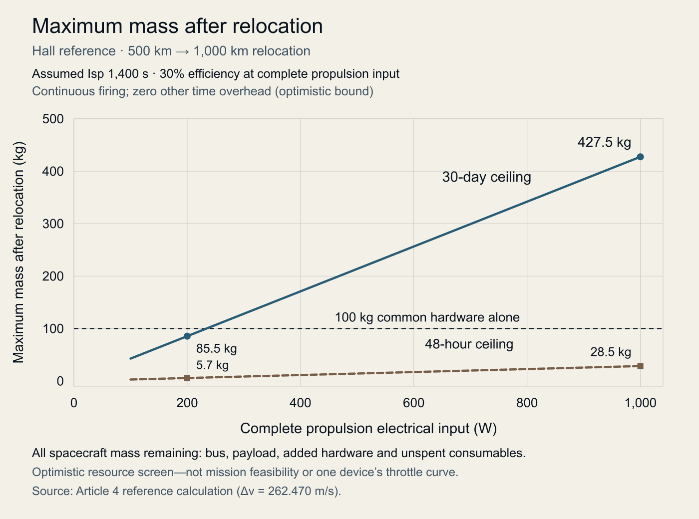
The assumed operating point matters. At 200 W, changing effective efficiency from 25% to 40% changes the normalized powered duration from 42.1 to 26.3 days. At the 40% point, a 30-day continuous-firing budget permits about 114 kg of retained spacecraft mass: only about 14 kg beyond the common 100 kg bus for all added hardware and retained consumables, with no other readiness delay. This sensitivity is not an established efficiency range for a particular thruster.
Firing availability is part of the time budget
If firing is permitted for only 70% of elapsed time, 7.0 powered days consumes approximately 10.0 days in a simple availability budget, before separate preparation and readiness allowances. The 70% value is illustrative, not a calculated eclipse fraction. Actual firing windows may also change the trajectory and required velocity increment; this arithmetic does not replace that analysis.
The comparison therefore carries two different findings forward: the chosen chemical thrust levels imply much shorter powered durations, while the selected Hall reference trades low propellant consumption against electrical allocation and operating time. Neither finding alone establishes a complete mission solution. Next, the installation comparison asks what equipment and retained consumables the spacecraft must carry to realize those operating points.
4. When propellant savings become spacecraft savings
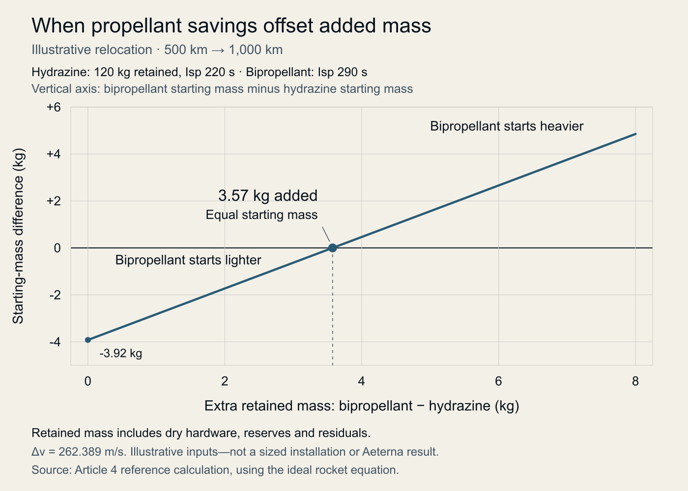
The propellant comparison held the mass remaining after the maneuver equal. We can now ask a different question: how much additional retained mass could the bipropellant spacecraft accommodate before its initial-mass advantage disappears?
For the same 262.389 m/s reference maneuver and the selected 220 s and 290 s specific impulses, equating initial masses using the rocket equation gives a 2.98% additional retained-mass allowance for the bipropellant reference. This allowance includes equipment and consumables remaining onboard after relocation.
To illustrate the scale, suppose the hydrazine-reference spacecraft retains 120 kg: the 100 kg common bus plus an assumed 20 kg of propulsion installation and retained consumables. That 20 kg is a numerical illustration, not an equipment estimate.
| Quantity | Hydrazine reference | Bipropellant at mass break-even |
|---|---|---|
| Mass remaining after relocation | 120.0 kg | 123.6 kg |
| Maneuver propellant expelled | 15.5 kg | 11.9 kg |
| Initial spacecraft mass | 135.5 kg | 135.5 kg |
Values are rounded to 0.1 kg. The calculated extra allowance is 3.57 kg, or approximately 3.6 kg. Below that net extra retained mass, the bipropellant spacecraft starts lighter; above it, it starts heavier. The calculation already includes the propellant needed to move the additional mass.
The allowance is not automatically an extra 3.6 kg of dry hardware. Additional retained reserves or unusable residuals consume part of it. Conversely, reductions elsewhere in the installation count in its favor. The comparison must also preserve the same required remaining mission capability; equal reserve kilograms do not establish equal future maneuver capability.
What belongs in the installation comparison?
| Contribution | What the comparison must establish |
|---|---|
| Storage and feed | Net mass and volume of tanks, pressurization hardware, valves, plumbing, supports and retained consumables—not simply the number of propellant tanks. |
| Power and thermal equipment | Additional equipment needed to supply the operating point and maintain required temperatures. The 1,000 W electric case must include any incremental generation, storage, conversion and thermal hardware it requires. |
| Readiness | Preparation, ready-standby and firing resources evaluated from comparable initial conditions. A fresh catalyst preheat before every pulse cannot be assumed, nor can instantaneous readiness for the bipropellant case. |
Added hardware feeds back into the calculation: it increases the mass that must be accelerated and therefore the required propellant and powered duration. The 7.0-day electric result, for example, remains a per-100-kg reference, not a time prediction for a heavier installation.
Mass and volume remain separate constraints. An installation can satisfy the mass comparison without fitting the spacecraft's available volume. Neither constraint has been resolved here by choosing actual equipment.
For this relocation, the bipropellant propellant saving provides a quantified allowance for additional retained mass. Whether that produces a lighter spacecraft depends on the complete configuration. Whether it produces a better mission solution also depends on readiness and operating capability, which remain to be established. This is a mass comparison for the selected references, not a demonstration of lifetime maneuvering performance.
5. Choosing for the operations that follow
A spacecraft expected to continue maneuvering must also be assessed against the sequence of operations after relocation:
- Readiness: How much preparation is permitted before a maneuver, and what must remain powered between maneuvers?
- Repeatability: What impulse and timing tolerances must be met across short firings and changing feed and thermal conditions?
- Endurance: What combination of starts, accumulated firing time and storage must the installed system support?
These are requirements to specify and verify for the intended installation, not capabilities established by the relocation calculation. A mission with frequent, time-constrained maneuvers may justify a different installation from one with long transfer windows and substantial propulsion power available. This comparison has not modeled that later operating history.
Bipropellant has a substantive case to carry into the next design stage: at the illustrative 10 N thrust level, the selected reference combines short powered duration with lower maneuver propellant consumption than the hydrazine reference. Its propellant saving provides an allowance for additional retained mass, not a guaranteed reduction in initial spacecraft mass. Realizing that combination in an operational spacecraft depends on the feed system, thermal behavior, controls and hardware capabilities. The next article examines those architecture choices.
These considerations inform Aeterna's development of bipropellant propulsion for spacecraft requiring frequent maneuvering and sustained operation. Repeatability, readiness and endurance are central development objectives.
Calculation and reference notes
Orbit model
The transfer values were calculated for this article using Earth's central gravity alone, excluding drag, other perturbations and rendezvous or phasing requirements. The adopted reference radius is 6,378.137 km and gravitational parameter is 398,600.4418 km³/s², from NGA's WGS 84 defining parameters. The two circular-orbit radii are therefore 6,878.137 km and 7,378.137 km.
The ideal Hohmann reference sums two tangential impulses, 132.345 and 130.043 m/s, connecting the circular orbits through a transfer ellipse; NASA's trajectory introduction explains the transfer geometry. For the slow, near-circular tangential spiral, integrating the change in circular-orbit energy gives the approximation , or 262.470 m/s. Neither reference is a propagated finite-thrust trajectory.
Specific-impulse input provenance
These sources inform individual scalar assumptions, not four selected commercial installations. The comparison does not establish supplier performance for this mission or predict Aeterna hardware performance.
- 70 s cold gas: nominal nitrogen specific impulse in Moog's 58E163A entry. Moog cold-gas datasheet, PDF p. 2.
- 220 s hydrazine: nominal specific impulse of ArianeGroup's 1 N hydrazine thruster. ArianeGroup monopropellant brochure, PDF p. 6.
- 290 s bipropellant: an illustrative value rounded from ArianeGroup's 292 s nominal 10 N MMH/NTO-family benchmark. It is not an N2O/hydrocarbon or Aeterna performance claim. ArianeGroup bipropellant brochure, PDF p. 4.
- 1,400 s Hall: an illustrative approximation informed by Busek's 1,390 s BHT-200 point and 1,300–1,500 s BHT-600 range. The calculation assumes effective specific impulse on a total-expelled-propellant basis, including cathode consumption; it is not a reconstructed supplier operating point. Busek BHT-200; BHT-600 datasheet.
This article is an educational discussion of public sources and original illustrative calculations. It does not report Aeterna hardware performance, qualification or flight results. Aeterna’s propulsion and fluid-control programs are in development.
← Article 3: From mission objectives to maneuver requirements